Introduction
After a lot of mathematics and python coding, you could wonder if there are limitation to the capabilities of what has been developed in the previous articles. Starting from the finite element formulation applied on the Helmholtz equation, the full working code for Direct Frequency Response, Modal Analysis and Modal Superposition have been described.
Such tools have been examined in detail, but the application were quite simple (rectangles and parallelepipeds). This choice made it possible to focus on the efficiency of the code and the analytical derivation.
Once this is done, the same code can be used while importing a complete different shape. What do you think if such shape is a a Chevrolet Corvette cabin?
Acoustic modal analysis is a fundamental tool in automotive cabin design. In order to guarantee the best comfort for the final customer, carmakers have to be sure that:
- the acoustic modes are damped as best as possible. A very strong acoustic resonance can be very annoying from a psychoacoustic point of view. Just speaking could become a nightmare.
- the sound sources spectra (engine, exhaust system, HVAC and speakers) don’t couple with the the modes, avoiding very bad phenomena, like booming noise.
Before starting, I need to point out that I am aware of how a pure modal analysis (performed with rigid walls) is not enough to characterize the acoustic behavior of a car cabin, that is wrapped with a lot of materials that increase mode’s damping.
Modal analysis is just the beginning of a more complete acoustic analysis, that has to be followed by a direct frequency response, in which a surface impedance is specified for every wall.
In order to be rigorous, a complete vibro-acoustic analysis should be performed, in order to take into account also the sound transmission and the fluid-structure interaction.
When such tools are ready (I am working on them!), such analyses will be performed and described in this blog. Stay tuned!
Geometry and Mesh
The CAD has been downloaded from Doğukan Uludağ’s GRABCAD profile. Check it out here! Once it was imported in Freecad, it looked like this:
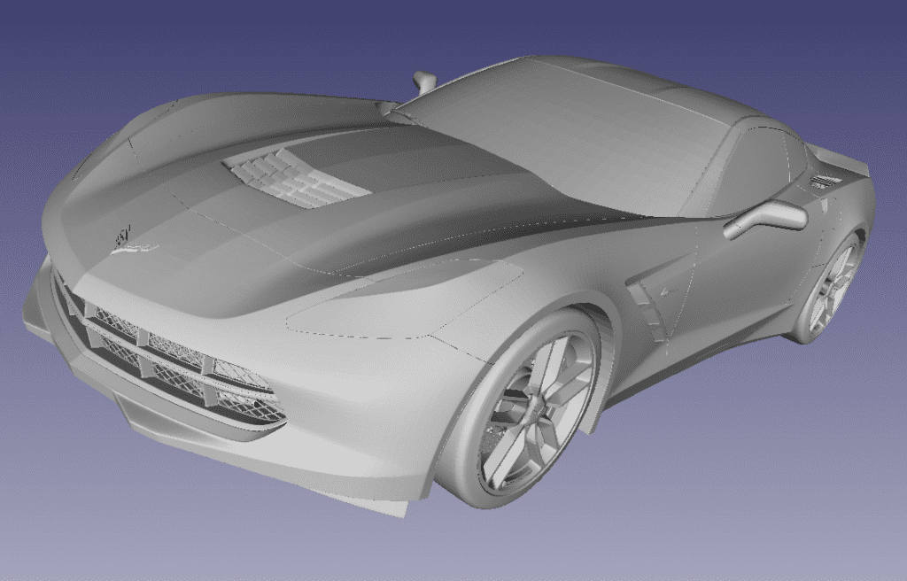
Since the parts were defined in details, it has been quite straightforward to isolate the cabin and extract its volume, exported in STEP format.
The volume geometry has been imported in gmsh, where the element dimension was set to 50 mm. This resulted in a 26881 Nodes, 117332 elements tetrahedral mesh. It was exported in .msh format, in order to be read from FEniCSx.
If you want more details on how to set a modal analysis in FEniCSx, check the realted article here. I am using the exact same code, with no change at all!
Results
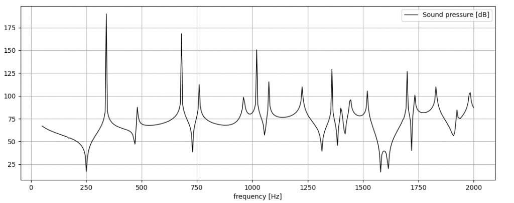
After the run, the modes up to 500 Hz have been extracted. Some of them are shown below:
As you can see, the mode shapes are not trivial. A lot of the symmetry of the perallelepiped is lost and the nodal surfaces (you can’t call them “planes” anymore!) seem to be random. This analysis already tells where the critical point are located in space at each frequency. If a source is located in one of the “lobes”, will result in an acosutic resonance at the corresponding frequency.
With such an analysis, the capabilities of an open source software like FEniCSx have been shown. It is not limited only to simple geometries, but it can be used for industrial applications.
The purpose of the blog is, on one hand, to talk about computational acosutics staying close to the maths and the code but, on the other, all the work aims to perform such analyses on real engineering problems.
Analytical mind on real problems!