Introduction
In the last (and first) article we talked about the Helmholtz equation and its implementation in FEniCSx for the solution of a point source propagating in a square 2D room. In that case no boundary conditions were specified, making the walls automatically rigid (that is, the natural boundary condition for the acoustic Helmholtz equaition).
This time we are going to define the acoustic boudnary condition and their physical meaning, choosing one of them for the implementation in FEniCSx.
Lets suppose that \partial \Omega is the boudnary of our computational domain. We can define three types of boundary conditions, as follows:
- Dirchlet conditions impose a specific value of \tilde{p} on \partial \Omega_{D}
\tilde{p}=p_{D} \quad\quad \text{on} \quad \partial\Omega_{D},
It is not the most common in acosutics, but it can be useful in a virtual Kundt tube, in which it can replace the speaker.
- Neumann conditions specify a normal particle velocity v_{n} on \partial \Omega_{N},
v_{n}=-\frac{1}{j\rho_{0}\omega}\frac{\partial p}{\partial n}= \bar{v}_{n} \quad\quad \text{on} \quad \partial\Omega_{N},
where n is the outward normal vector of the boundary surface. It is the most rigorous way to take into account source generation, that is always caused by velocity oscillations (due to fluid or solid) that propagate as sound waves.
- Robin conditions specify an acoustic impedance Z on \partial \Omega_{R} as well as an optional particle velocity.
p=Zv_{n}=-\frac{Z}{j\omega\rho_{0}}\frac{\partial p}{\partial n}= -\frac{1}{j\omega\rho_{0}A}\frac{\partial p}{\partial n}\quad\quad \text{on} \quad \partial\Omega_{R}
This is maybe the most famous boundary condition, since its concept is widely applied in all the branches of the Acoustics (not only the computational one). It is known to represent the effect of non-rigid walls on the propagation of sound inside cavities. Porous layers, metamaterials and every absorber element in general is taken into account with its surface impedance.
The Helmholtz equation in its “complete” weak form
The weak form of the Helmholtz equation, considering also the boundary conditions, is the following:
\int_{\Omega}\nabla w \cdot \nabla p d\Omega – \int_{\Omega}k^{2}wp d\Omega = \int_{\Omega}j\omega\rho_{0} w q d\Omega +\oint_{\partial\Omega}w \frac{\partial p}{\partial n} dS
In which the last term on the RHS contains the value of the flux of p through the domain’s boundary. This means that both Neumann and Robin boundary conditions definition is straightforward. The specification of Dirichlet boundary condition, on the other side, is made directly on the final form of the problem (linear system of algebraic equations).
Let’s focus on the impedance boudnary condition. We defined Z as the ratio between sound pressure p and particle velocity v_{n}. This allows from the formula shown above, we can then derive the flux \frac{\partial p}{\partial n} as follows:
\frac{\partial p}{\partial n}=-\frac{j\omega\rho_{0}}{Z}p
The weak form of the Helmholtz equation becomes, with the impedance boudnary condition:
\int_{\Omega}\nabla w \cdot \nabla p d\Omega – \int_{\Omega}k^{2}wp d\Omega = \int_{\Omega}j\omega\rho_{0} w q d\Omega -\oint_{\partial\Omega} \frac{j\omega\rho_{0}}{Z}wp dS
The last term is written on the LHS of the equation, since it contains p. It will represent the damping matrix in the final system of linear equations:
\int_{\Omega}\nabla w \cdot \nabla p d\Omega – \int_{\Omega}k^{2}wp d\Omega + \oint_{\partial\Omega} \frac{j\omega\rho_{0}}{Z}wp dS = \int_{\Omega}j\omega\rho_{0} w q d\Omega
FEniCS implementation
This time I will not go through all the code, but I will show you which modifications to make to the previous code in order to implement BC in fenics.
First of all, we need to import the UFL representation of dS for the surface integral definitions. The new import will look like this:
from ufl import dx, grad, inner, dsIn this example, we will stick with the monopole source defined in the previous article and apply the spherical wave impedance to all the boundaries. First of all, we need to create a function r that defines the radial distance from the source. Then, we write the formula of the impedance that is:
Z = \frac{\rho_{0}c_{0}}{1+\frac{1}{jk_{0}r}}
following, its implementation:
r = Function(V)
r.interpolate(lambda x : np.sqrt((x[0]-Sx)**2 + (x[1]-Sy)**2))
Z = rho_0*c0/(1+1/(1j*k0*r))
Finally we can write the weak form of the Helmholtz equation with an impedance boundary condition
f = 1j*rho_0*omega*Q*delta
g = 1j*rho_0*omega/Z
a = inner(grad(u), grad(v)) * dx - k0**2 * inner(u, v) * dx +  g * inner(u , v) * ds
L = inner(f, v) * dx
The rest of the code remains exactly the same. If you want the full working code, you can write me here. I will be happy to give it to you.
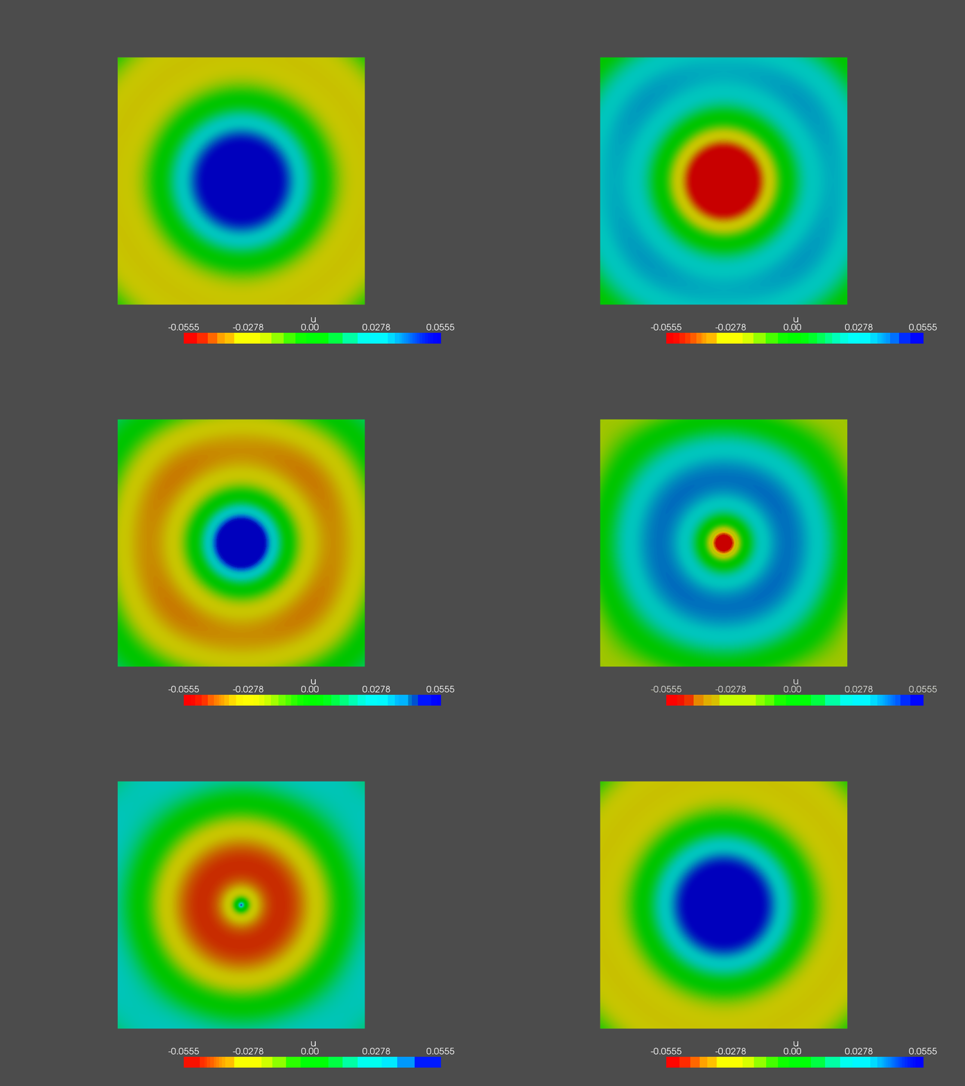
Since we applied a sperical wave impedance condition on the boundary of our domain and the load is a point source, we expect to see a spherical propagating wave for every frequency. These are some examples of the solution:
400 Hz
1500 Hz
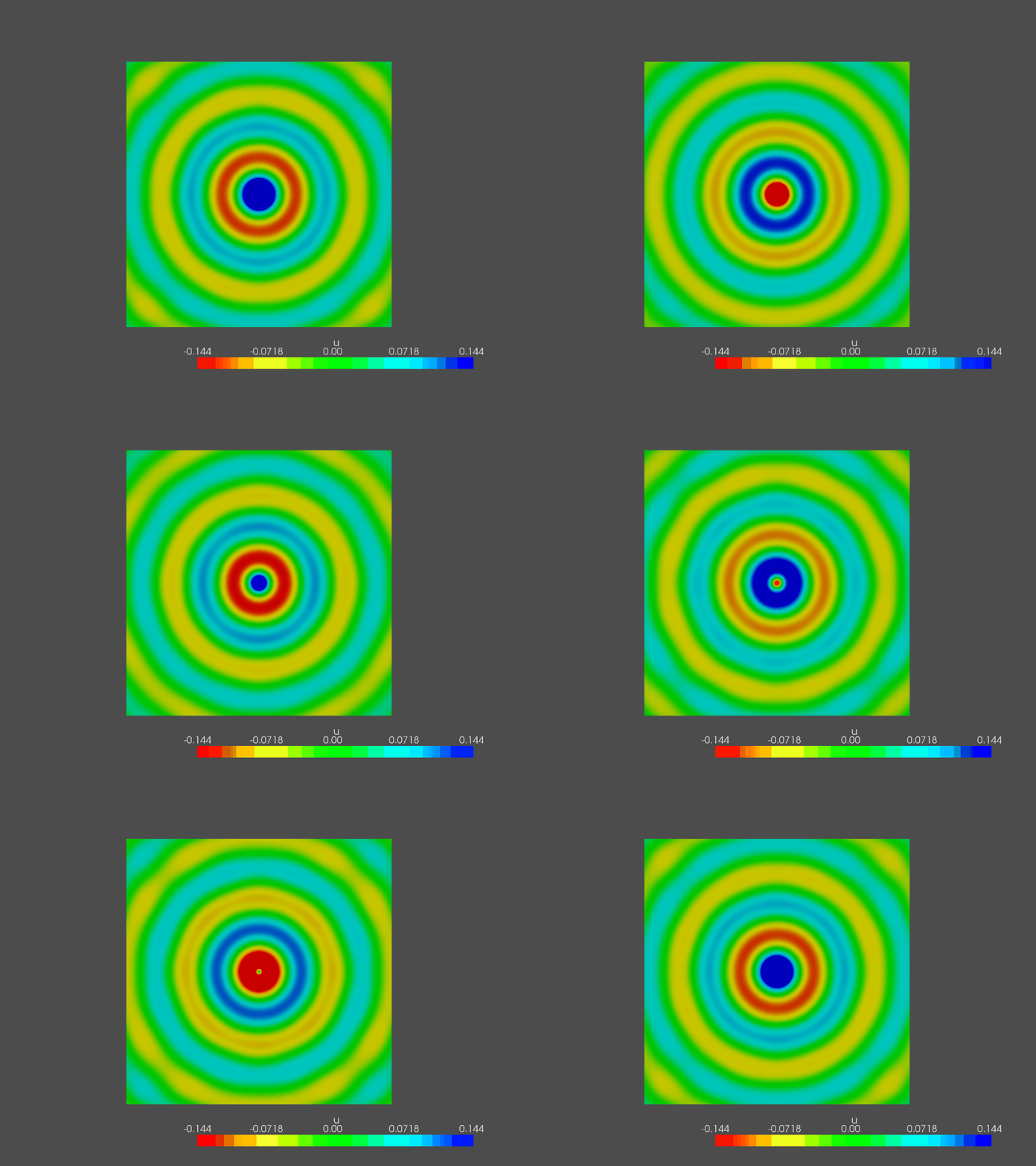
2000 Hz
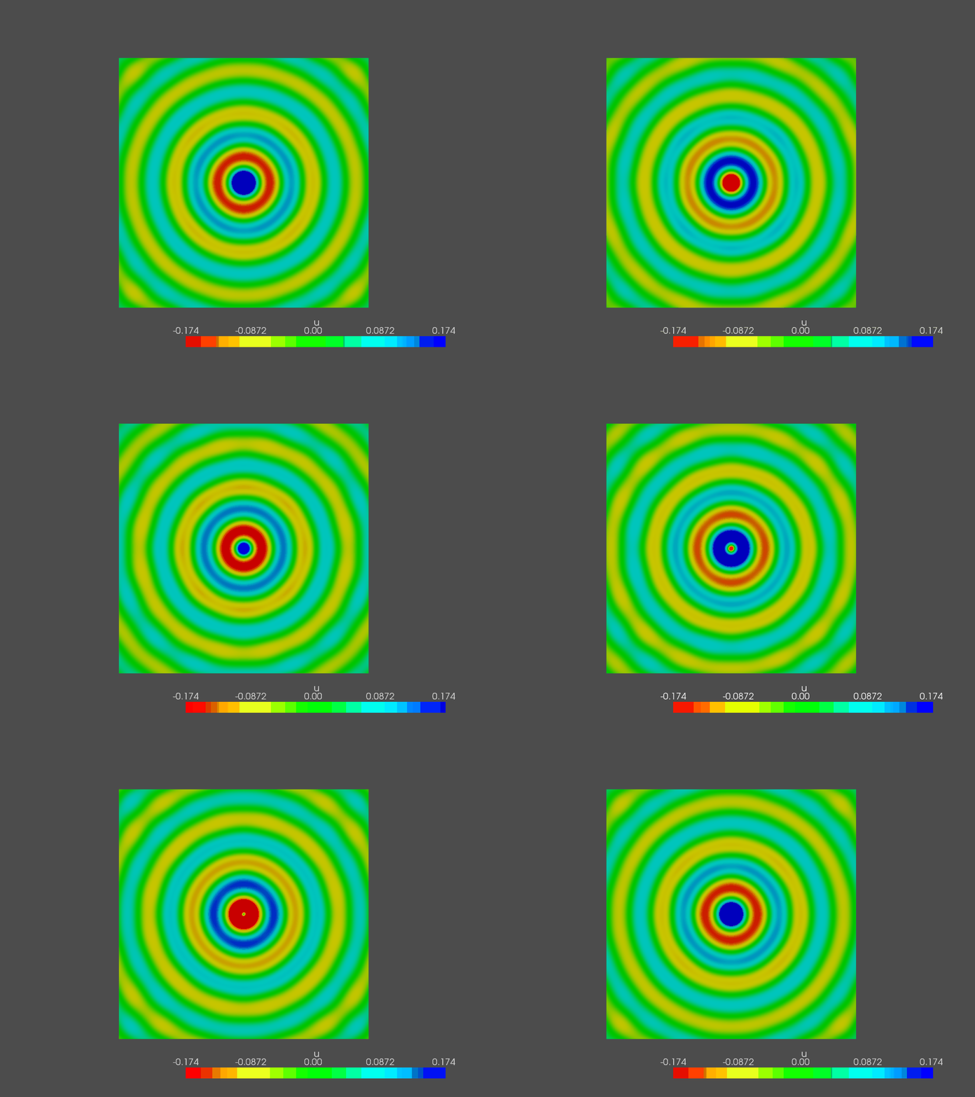
You can clearly notice a bit of distortion in the wave, that is not perfectly spherical. This is due to the fact that the domain’s boundary is a square: the numerical error propagates just as the normal wave, but its reflected part depends on the incidence of the wave on the wall. This is what causes the wave’s distortion. If we make a circular boundary all of these effects disappear, making the solution more regular.
Since, in general, we cannot make the boundary have the same shape of the outgoing wave, most powerful tools are used to simulate free field radiation, such as Perfectly Matched Layers, that will be a good topic for future articles.
For now, play with BC in FEniCSx and see their effect on the sound field!
