Introduction
Mufflers play a crucial role in reducing the noise generated by internal combustion engines and other machinery. The study of acoustic simulation in mufflers offers valuable insights into their performance and effectiveness. In this article, we will show how open-source software, in 2023, allows to simulate any “real-world” system.
How mufflers work
The effect of a muffler involves a combination of physical principles and engineering techniques to attenuate sound waves. Here’s a simplified explanation of how a muffler works and how it reduces noise:
- Perforated Tubes or Baffles: Inside the muffler, there are typically perforated tubes or baffles that direct the exhaust gases through a series of channels. These tubes or baffles are designed to create turbulence and cause the sound waves to interact with each other.
- Sound Wave Interference: As the exhaust gases pass through the perforated tubes or baffles, sound waves are generated. These sound waves then interact with each other, leading to destructive interference.
- Absorptive Materials: Mufflers often include sound-absorbing materials, such as fiberglass or steel wool, surrounding the perforated tubes or baffles. These materials help to absorb and dissipate sound energy by converting it into heat.
- Multiple Chambers: Some mufflers feature multiple chambers with variations in design, including different lengths and sizes of tubes or baffles. This multi-chamber configuration further enhances sound wave cancellation and absorption, resulting in greater noise reduction.
- Tailpipe Diffuser: At the end of the muffler, there is a tailpipe diffuser, which helps to smoothly release the exhaust gases into the atmosphere. The diffuser also plays a role in reducing the backpressure caused by the muffler, which can have a negative impact on engine performance.
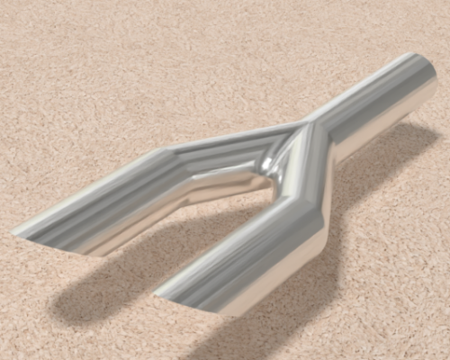
In this article, we will compute the sound pressure field (using FEniCSx) of the following muffler:

The geometry was designed by Adrian Catalin and downloaded from his grabcad profile.
In our muffler simulation, we implemented a volume velocity condition at the inlet with a value of 0.001 m3/s. The volume velocity represents the flow rate of fluid entering or leaving a specific volume.
In order to simulate the muffler in free air, a spherical geometry was added to the muffler CAD. This sphere is necessary for the automatic generation of the Perfectly Matched Layer (PML).

The quasi-spherical surfaces have been selected as PML surfaces, and the auto-generating PML script handled all the work. The walls of the muffler were considered rigid for the sake of simplicity. However, in future iterations, we plan to solve the same problem while taking into account the structure-acoustic coupling. Stay tuned for updates!
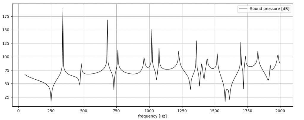
A virtual microphone has been positioned at the outlet of the muffler to calculate the pressure spectrum within the 50-3000 Hz range. This is the result:

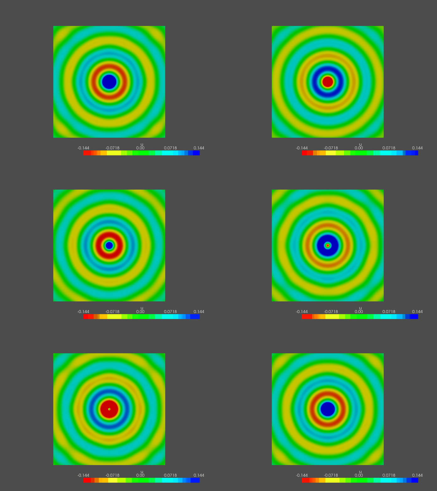
Follows an example of pressure contours (here, 1500 Hz):

To analyze the impact of the muffler on the sound spectrum, a “dummy” tube was designed fixing the same inlet and two outlets. This allows us to isolate and study the specific effects of the muffler on the sound spectrum.

Applying the same boundary condition (both velocity and PML), we get a pressure spectrum that can be compared with the previous one:

It is evident that the muffler has a significant impact, as the difference between the two sound levels remains, on average, around 20 dB. This indicates that the muffler plays a crucial role in attenuating the sound and reducing the overall noise level. Below, this difference is plotted:

Finally, I would like to highlight the incredible capabilities of open-source software in simulating real systems. Every single thing you’ve seen so far was accomplished using these powerful tools. For geometry modeling, I utilized FreeCAD, while gmsh handled the meshing process. The simulation itself was carried out using FEniCSx. And not to be forgotten, Paraview played a crucial role, enabling us to create stunning visualizations, including the captivating video demonstrated below:
I hope that you found this application interesting. See you next time!


This is awesome, keep up with the education part of this project!